- 您现在的位置:买卖IC网 > Sheet目录3828 > DSPIC30F4012-20I/SO (Microchip Technology)IC DSPIC MCU/DSP 48K 28SOIC
dsPIC30F4011/4012
DS70135G-page 154
2010 Microchip Technology Inc.
21.2
Oscillator Configurations
21.2.1
INITIAL CLOCK SOURCE
SELECTION
While coming out of Power-on Reset or Brown-out
Reset, the device selects its clock source based on:
a)
The FOS<1:0> Configuration bits that select one
of four oscillator groups.
b)
The FPR<3:0> Configuration bits that select one
of 13 oscillator choices within the primary group.
The selection is as shown in Table 21-2.
21.2.2
OSCILLATOR START-UP TIMER
(OST)
In order to ensure that a crystal oscillator (or ceramic
resonator) has started and stabilized, an Oscillator
Start-up Timer (OST) is included. It is a simple, 10-bit
counter that counts 1024 TOSC cycles before releasing
the oscillator clock to the rest of the system. The time-
out period is designated as TOST. The TOST time is
involved every time the oscillator has to restart (i.e., on
POR, BOR and wake-up from Sleep). The Oscillator
Start-up Timer is applied to the LP, XT, XTL and HS
modes (upon wake-up from Sleep, POR and BOR) for
the primary oscillator.
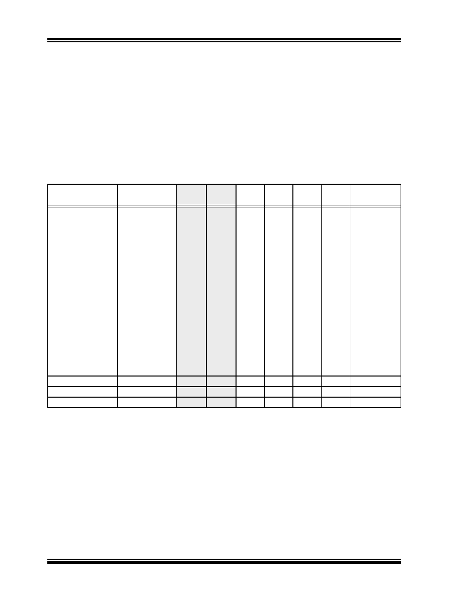
TABLE 21-2:
CONFIGURATION BIT VALUES FOR CLOCK SELECTION
Oscillator Mode
Oscillator
Source
FOS1
FOS0
FPR3
FPR2
FPR1
FPR0
OSC2
Function
EC
Primary
1
11
0
1
CLKO
ECIO
Primary
1
11
1
0
I/O
EC w/PLL 4x
Primary
1
11
1
0
1
I/O
EC w/PLL 8x
Primary
1
11
1
0
I/O
EC w/PLL 16x
Primary
1
11
1
I/O
ERC
Primary
1
11
0
1
CLKO
ERCIO
Primary
1
11
0
I/O
XT
Primary
1
10
1
0
OSC2
XT w/PLL 4x
Primary
1
10
1
0
1
OSC2
XT w/PLL 8x
Primary
1
10
1
0
OSC2
XT w/PLL 16x
Primary
1
10
1
OSC2
XTL
Primary
1
10
0
OSC2
HS
Primary
1
10
0
1
0
OSC2
FRC w/PLL 4x
Primary
1
10
0
1
I/O
FRC w/PLL 8x
Primary
1
11
0
1
0
I/O
FRC w/PLL 16x
Primary
1
10
0
1
I/O
LP
Secondary
0
——
(Notes 1, 2)
FRC
Internal FRC
0
1
——
(Notes 1, 2)
LPRC
Internal LPRC
1
0
——
(Notes 1, 2)
Note 1:
OSC2 pin function is determined by the Primary Oscillator mode selection (FPR<3:0>).
2:
Note that the OSC1 pin cannot be used as an I/O pin, even if the secondary oscillator or an internal clock
source is selected at all times.
发布紧急采购,3分钟左右您将得到回复。
相关PDF资料
DSPIC33FJ64MC204-E/PT
IC DSPIC MCU/DSP 64K 44-TQFP
DSPIC30F4012-30I/SO
IC DSPIC MCU/DSP 48K 28SOIC
HM2H08P117LF
HM2H08P117LF SHROUD STYLE B LF
PIC18LF4423-I/ML
IC PIC MCU FLASH 8KX16 44QFN
ATTINY44V-10PU
IC MCU AVR 4K FLASH 10MHZ 14-DIP
PIC16F77-I/P
IC MCU FLASH 8KX14 A/D 40DIP
MP2-HS024-43
CONN SHROUD 2-FB 24POS 4ROW
ATTINY44V-10MU
IC MCU AVR 4K FLASH 10MHZ 20-QFN
相关代理商/技术参数
DSPIC30F4012-20I/SP
功能描述:数字信号处理器和控制器 - DSP, DSC 16 Bit MCU/DSP 28LD 20M 48KB FL RoHS:否 制造商:Microchip Technology 核心:dsPIC 数据总线宽度:16 bit 程序存储器大小:16 KB 数据 RAM 大小:2 KB 最大时钟频率:40 MHz 可编程输入/输出端数量:35 定时器数量:3 设备每秒兆指令数:50 MIPs 工作电源电压:3.3 V 最大工作温度:+ 85 C 封装 / 箱体:TQFP-44 安装风格:SMD/SMT
DSPIC30F4012-20I/SP
制造商:Microchip Technology Inc 功能描述:16BIT MCU-DSP 20MHZ 30F4012 SDIL
DSPIC30F4012-30I/ML
功能描述:数字信号处理器和控制器 - DSP, DSC Motor Control RoHS:否 制造商:Microchip Technology 核心:dsPIC 数据总线宽度:16 bit 程序存储器大小:16 KB 数据 RAM 大小:2 KB 最大时钟频率:40 MHz 可编程输入/输出端数量:35 定时器数量:3 设备每秒兆指令数:50 MIPs 工作电源电压:3.3 V 最大工作温度:+ 85 C 封装 / 箱体:TQFP-44 安装风格:SMD/SMT
DSPIC30F4012-30I/SO
功能描述:数字信号处理器和控制器 - DSP, DSC 16 Bit MCU/DSP 28LD 30M 48KB FL RoHS:否 制造商:Microchip Technology 核心:dsPIC 数据总线宽度:16 bit 程序存储器大小:16 KB 数据 RAM 大小:2 KB 最大时钟频率:40 MHz 可编程输入/输出端数量:35 定时器数量:3 设备每秒兆指令数:50 MIPs 工作电源电压:3.3 V 最大工作温度:+ 85 C 封装 / 箱体:TQFP-44 安装风格:SMD/SMT
DSPIC30F4012-30I/SO
制造商:Microchip Technology Inc 功能描述:16- Bit Digital Signal Controller Memory
DSPIC30F4012-30I/SP
功能描述:数字信号处理器和控制器 - DSP, DSC 16B MCU/DSP 28LD 30M 48KB FL RoHS:否 制造商:Microchip Technology 核心:dsPIC 数据总线宽度:16 bit 程序存储器大小:16 KB 数据 RAM 大小:2 KB 最大时钟频率:40 MHz 可编程输入/输出端数量:35 定时器数量:3 设备每秒兆指令数:50 MIPs 工作电源电压:3.3 V 最大工作温度:+ 85 C 封装 / 箱体:TQFP-44 安装风格:SMD/SMT
DSPIC30F4012-30I/SP
制造商:Microchip Technology Inc 功能描述:16- Bit Digital Signal Controller Memory
dsPIC30F4012T-20E/ML
功能描述:数字信号处理器和控制器 - DSP, DSC 44LD 20MIPS 48 KB RoHS:否 制造商:Microchip Technology 核心:dsPIC 数据总线宽度:16 bit 程序存储器大小:16 KB 数据 RAM 大小:2 KB 最大时钟频率:40 MHz 可编程输入/输出端数量:35 定时器数量:3 设备每秒兆指令数:50 MIPs 工作电源电压:3.3 V 最大工作温度:+ 85 C 封装 / 箱体:TQFP-44 安装风格:SMD/SMT